In the last news, a design method of large-size strip ultrasonic plastic welding slotted joint was proposed and verified by experiments. Firstly, the strip welding horn is reasonably divided into several units so that the design of slotted welding horn with complex structure is transformed into the design of simple welding horn unit. Then the joint element is compared with the half wave oscillator with equal section considering coupling vibration. The frequency equation of the joint is obtained by using the concept of equivalent mechanical impedance.
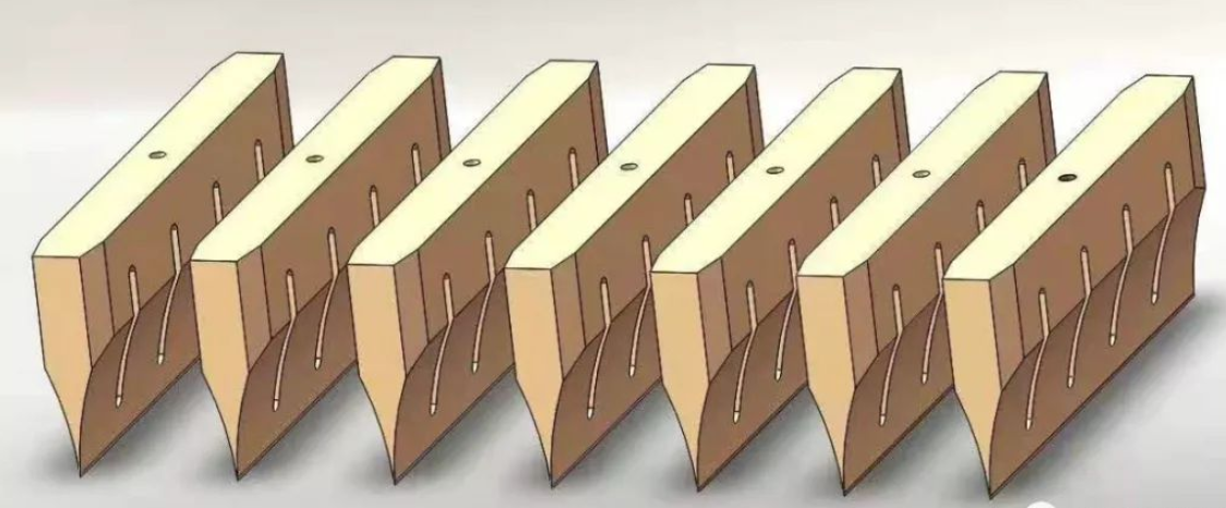
Finally, the influence of slot number, slot width and slot length on the vibration characteristics of welding joints was studied by using the equation. According to this method, several groups of large size strip grooves were designed and machined. The experimental results show that the measured and theoretical values of the resonance frequency of the welded joints are in good agreement.
As shown in the figure below. The length, width and thickness of the welding horn are L, B and T respectively. Assume z axis as the excitation direction of the transducer. At the working frequency, the rectangular welding joint will produce first-order longitudinal vibration in the Z direction. For strip welding joints, L≥2T, B and L can be compared, so the transverse vibration of the welding joints in the X direction can be ignored.
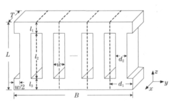
Because the transverse vibration in y direction has great influence on the longitudinal vibration, it is usually simulated by slotting. The welding horn is divided into (n+1) units by uniformly opening n slots in the Y direction. The width and length of each slot are W and L2 respectively, and the slots are separated from the input and output ends of the welding horn l1 and L3 respectively. To ensure that each unit is completely equal, grooves of width W /2 should be opened at both ends of the transverse welding horn. Thus, each welding mould unit is a compound trapezoidal horn with a rectangular section. Assuming that the width at both ends and in the middle of each unit is D1 and D2, it can be seen from the above: L= L1 + L2 +L3
Due to the same pattern between the elements, the output amplitude of the weld will also vibrate the pattern, and when combined, the ultrasonic horn will also have this pattern, so that the design of the ultrasonic mould will be simplified to the design of any element. In addition, it is relatively uniform. In order to effectively suppress the transverse vibration and ensure that the welding horn has a fixed stiffness, the width of the welding horn unit divided by the groove is generally in! / 8 ~! / 4 (! Is the wavelength of the first-order longitudinal vibration mode of the welding horn), and the ideal width of the slot is about! / 25 ~! /20[7], the grooving number of welding joints can be determined according to the above criteria. Because the width of the welding horn unit generally does not exceed! PI /4, so it can be approximately analyzed by one-dimensional theory. Any welding unit in unit 1 can be regarded as consisting of three rectangular equisectional bars.
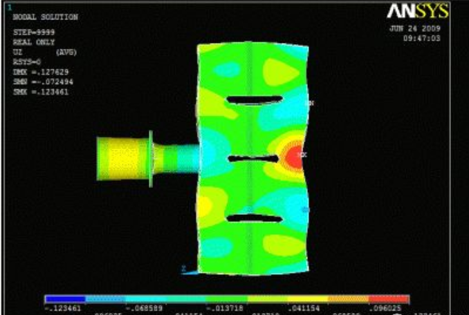
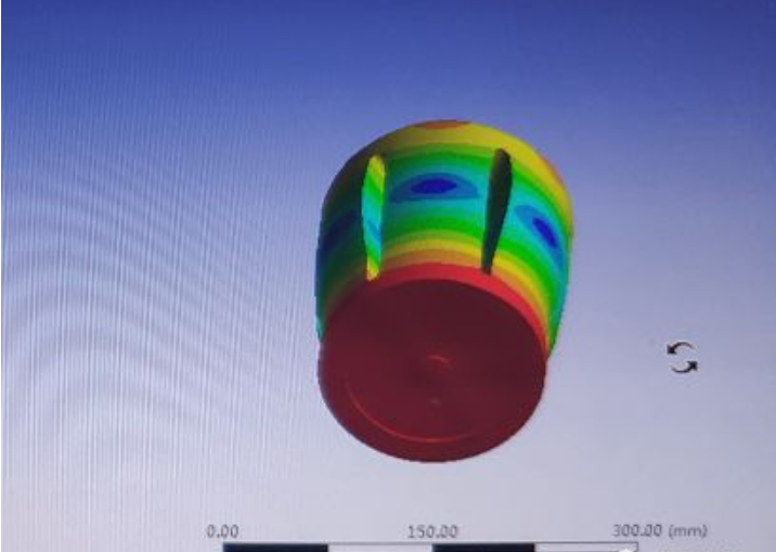
Aluminum alloy 7075 (Young’s modulus E=7.17*1010N/M2 density ρ=2820kg/m3, Poisson’s ratio V =0.34) was selected for welding horn. Equations (1) ~ (3) and (6) were used to calculate the number n, length L2 and width W of different slots. When the resonant length L of the strip welding horn changes with the width B, the resonant length L of the strip welding horn changes with the width B. The calculated resonant frequency f=20kHz, L1=L3 for simplicity. When the slot length and width are constant, the resonant length changes with the weld horn width when the slot number is different. L2 =60mm, W =10mm. As can be seen from FIG. 2, for the slotted welding horn shown in FIG. 1, the first-order resonance length is smaller than that of the unslotted welding horn calculated according to one-dimensional theory (126mm), and the resonant length of the welding horn increases with the increase of the width of the welding horn, but the increase decreases gradually. In addition, when the resonant frequency and the weld width are constant, the resonant length of the weld decreases with the increase of the slot number.
In addition, three welded joints of different thickness were machined with aluminum alloy 7075(same material as above). The thickness T of these three welded joints and the measured harmonic vibration frequency FM were given. When the welding horn thickness is less than a quarter of the wavelength (here is 63mm), the deviation between the measured frequency and the design frequency is less than 2%, which can meet the requirements of engineering applications.
The long strip ultrasonic plastic welding joint was reasonably divided into several equal elements and the frequency equation of the joint element was deduced by transfer matrix method. If the width and the quantity and size of the slot are known, the equation can be used to design the strip joint conveniently, thus providing a theoretical basis for the design of the strip joint. This paper also analyzes the influence of slot number, slot width and slot length on the welding joint size through examples. It can be seen that this method also has a certain influence on the optimization design of the welding joint
Split groove after strip welding horn vibration analysis, the welding horn can be divided into the end unit body and middle unit cell, using the method of apparent elasticity method and effect of transmission line, the length of the four different units are given respectively and the direction of the high degree of frequency equation, the frequency equation can be used to design a long bar welding horn, but the design process is complicated, The selection of some parameters depends on experience and is not convenient for engineering application. In this paper, the strip welding joint is divided into several equal elements by reasonable slotting, and the frequency equation of the welding joint element is obtained by transfer matrix method, which provides a theoretical basis for the design of the strip welding joint. The design has simple theoretical calculation and obvious physical meaning, which provides a simple and easy method for the engineering design of strip
welding joint.
Post time: Mar-17-2022