In this example, the thermoplastic bonding method “ultrasonic plastic welding method” was used to predict the dynamic behavior of cylindrical plastic parts during the bonding process by dynamic contact analysis of finite element method, and the relationship between driving frequency and welding characteristics was evaluated.
1/Purpose of ultrasonic analysis
“Ultrasonic plastic welding method” is used in automobile parts, household appliances, medical equipment, packaging products and a wide range of fields, as a thermoplastic bonding method, through the ultrasonic horn to apply ultrasonic vibration to the plastic parts, generate surface friction at the joint and internal friction of the material generated heat, so as to melt the joint near the contact surface for welding. However, depending on the shape of the plastic part and the drive frequency of the welding device, the air tightness and strength of the welded part may not be sufficient, so if the dynamic behavior of the joint can be predicted and evaluated when the ultrasonic vibration is pre-applied, the part shape and drive frequency can be changed prior to prototyping for efficient welding.
Because the welding equipment used in the ultrasonic welding method uses ultrasonic horn resonance, its drive frequency is limited to discrete values, such as 15kHz, 20kHz and 25kHz. By predicting and evaluating the dynamic behavior of the joint when the ultrasonic vibration is applied in advance, the drive frequency with high welding effect can be selected for the corresponding welding sample.
Ultrasonic plastic welding is roughly divided into direct welding (short distance welding) and transfer welding, welding by transferring vibration to the welding sample, here we introduce transfer welding, with the expansion of welding application range, the demand for transfer welding is increasing. Because transfer welding usually involves complex plastic part shapes, and because of part deformation, the dynamic behavior of the joint can be complex. Therefore, it is difficult to evaluate the dynamic behavior of the joint in the experiment, and there are many restrictions, so it is necessary to build an analytical method that can evaluate the dynamic behavior of the joint in detail.
Here, we use the finite element method for dynamic contact analysis of cylindrical plastic parts to predict the dynamic behavior of joints. Combined with the actual welding experiment results, the influence of welding pressure (static pressure) on the important ultrasonic welding parts in actual welding and the reason why the dynamic behavior of welding parts varies with the driving frequency were discussed.
2 Ultrasonic welding experiment
Figure 1 shows the analysis goals for this analysis example. Place one plastic Part on the base and another plastic part (Upper Part) on the base. The ultrasonic Horn (Horn) is then pushed through the Upper Part to apply welding pressure (static pressure) to the Upper Part through the horn in the cylinder. When ultrasonic vibrations apply static pressure through the horn, they create friction at the joint contact surface between the components and generate internal heat near the contact surface, causing the plastic near the contact surface to melt and weld the joint.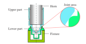
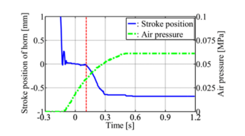
In the welding experiment, the application time of ultrasonic vibration is 0.5 seconds, and the air pressure (static pressure) remains 0.7 seconds after the ultrasonic application. In order to study the influence of drive frequency difference on the dynamic behavior of welded parts, we used two types of welding equipment: drive frequency 15kHz and 19kHz. At this point, welding devices with a drive frequency of 15kHz and 19kHz have different cylinder diameters and horn weights, so both will adjust the upper pressure limit so that the static pressure is about 500N. In addition, because ultrasonic welding uses horn resonance to amplify the amplitude, the amplitude of the horn tip is adjusted to 30μm with a frequency of 0.1sec from ultrasonic application. FIG. 2 shows the horn stroke position and pressure time variation during welding experiments on a welding device with a drive frequency of 15kHz. The horn stroke position of the vertical axis is based on the position of the horn tip in contact with the upper component, and the time of the horizontal axis represents the result before the end of the welding experiment based on the start time of the ultrasonic application.
In Figure 2, when the horn stroke position is 0 mm (for a time of about -0.1 seconds), the cylinder is pressurized and the air pressure gradually increases, with ultrasonic vibration beginning to be applied at 0 SEC when the air pressure is 0.018MPa (30% of the final pressure). Also, from the time shown by the dashed lines in the figure (drive frequencies 15kHz and 19kHz are both 0.11 seconds from ultrasonic application), you can see that the horn is suddenly pushed in, which means that the plastic near the joint begins to melt. In the following dynamic contact analysis, the analysis object is the dynamic behavior of the joint before melting of the plastic part. Considering the static pressure during the application of the ultrasonic wave, the static load used in the analysis is determined based on the air pressure before the joint begins to melt (dashed time position) in Figure 2.
In the welding experiment, the radial vibration displacement of measuring point A (upper part) and measuring point B (lower part) as shown in Figure 3 was measured by laser displacement meter (KEYENCE MY-H023, sampling frequency 200kHz)
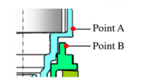
The comparison between the experiment and the analysis is the vibration displacement between 2 milliseconds before the plastic component begins to melt, i.e., before the dotted line in Figure 2.
3 Dynamic contact analysis of ultrasonic horn welding
Dynamic contact analysis evaluates the dynamic behavior of the joint before melting of plastic parts, i.e. the joint’s vibration displacement (including contact and sliding between parts) as well as the joint deformation (strain) and the sliding momentum and contact force of the joint’s contact surface. Figure 4. Shows a finite element (FE) model for dynamic contact analysis.
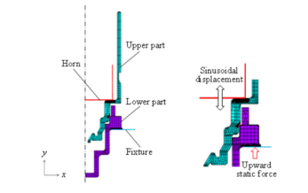
4 Finite element model for contact analysis
The analytical element was an axisymmetric two-dimensional four-node element (Plane182), the plastic material was POM (polyacetal) resin, Young’s modulus E=2.6GPa, Poisson’s ratio =0.35, the density ≥=1410kg/m3 was a certain value, the horn and the base were defined as rigid body. Figure 5. Represents the contact surfaces between the horn and the upper part, the upper part and the lower part, and the lower part and the base respectively.
The extended Lagrange method is used to form contact elements and uses the following contact forms at each contact position.
1. No friction between the horn and the upper part
2. Friction between upper and lower components (friction coefficient μ=0.4)
3. Fix it between the lower part and the base
5 How to ultrasonic mold analysis
In the welding experiment, the cylinder applies ultrasonic vibration while applying static load to the horn. Thus, ultrasonic vibrations of constant amplitude are applied when static loads are loaded onto the joint through the upper component. However, as the analysis condition, the force load (uniform) and forced displacement (vibration amplitude) cannot be applied to the horn (rigid body) at the same time, so the static load on the bearing platform (rigid body) upward force load (uniform), after solving the static equilibrium condition (initial condition), the horn (rigid body) forced displacement (vibration amplitude =30μm). The integrated time interval used for the time-historical response analysis is 1 period of the forced displacement sine wave amplitude, which is divided into 200 subparts and 50 periods are calculated. In order to improve the convergence of nonlinear problems, we use the automatic adjustment function of integration interval. In addition, as material damping characteristics, POM resin loss coefficient and so on.
If you are interested in our ultrasound experience, feel free to share with us.
Post time: Nov-19-2022